Features and structure
Proper dehydration by compacting depends on the following factors:
- Type of raw waters.
- Waste transported.
- Type of mesh or screen and its operating method.
There are three main components in a QUILTON hydraulic compactor: the compacting area, the hydraulic system, and the operating panel and switchboard.
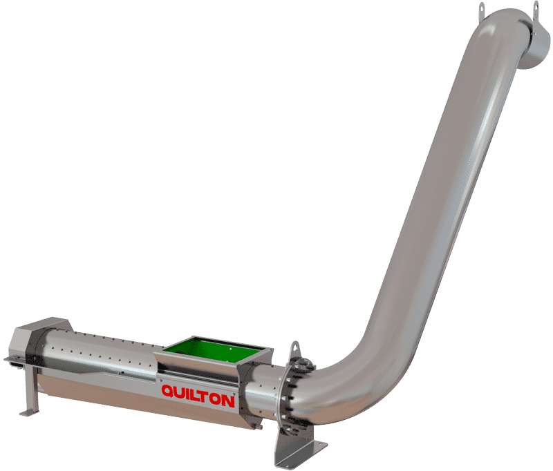
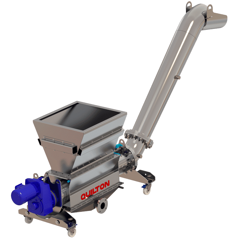
COMPACTING AREA
This basically involves a piston that moves slowly, alternating inside a tubular body mounted beneath a load hopper. The outlet of the tubular body is connected by a flange to the discharge pipe that compacts the wastes and offloads them at a certain distance or height from the compactor. There is a tray under the tubular body for collecting the liquids extracted from the wastes.
HYDRAULIC SYSTEM
This involves a hydraulic cylinder inside the compactor piston powered by the hydraulic drive, at a pressure that may vary between 100 and 200 bars. This pressure is converted into a pushing force ranging between 4,000 and 11,000 kg, depending on the piston diameter.
The hydraulic drive on a QUILTON hydraulic compactor is to be mounted in a dry area that is not susceptible to flooding under normal conditions. It has the following components:
- Filter.
- Oil temperature and level sensor.
- Pump.
- Manometer.
- Safety valve.
- Solenoid.
- Pressure gauge.
- Hydraulic cylinder.
OPERATING PANEL AND SWITCHBOARD
It is used to operate the hydraulic unit, regulate the number of cycles per minute, adjust and control the drive force, etc. If the pressure increases above the set value (caused by a body that is harder than the other wastes, such as a piece of wood) the piston withdraws and the cycle begins again, which avoids any blockage between the piston and the tubular body.
As with the hydraulic drive, it should be located in a dry area that is not susceptible to flooding.
Operation
A QUILTON hydraulic compactor is designed to operate in two settings: manual and automatic. In order to choose between these two settings, the operating panel has a switch with the following positions: automatic, stop and manual.
Manual setting: when the switch is turned to manual, the cylinder only operates when the "avance" (forward) or "retroceso" (back) buttons are pressed. Pressing the "avance" button starts the compression process. It will only operate in a forward direction while the "avance" button is being pressed. If the button is released, the piston stops immediately. Once it has completed its forward run, the pressure increases, but it does not withdraw.
Automatic setting: when the switch is turned to "Aut.", this activates the software installed on the programmable logic controller (PLC), which is enabled when the external signal terminals receive power. The compactor will continue performing cycles until no signal reaches the potential-free terminal; in other words, the upstream unit has stopped and, therefore, the PLC receives the order to stop.
Options in assembly and maintenance